Infrared distance measuring on the airtrack
a) Problem being adressed
When complicated movements of a cart of the airtrack need to be measured, the commonly used motion detector fails because of its limit to only five measurements per second. For accurate measuring, a more advanced device had to be developed.b) Hypothesis
The newly developed device is capable of up to 1000 measurements per second and is still as easy to operate as the motion detector.c) Description in detail of procedures
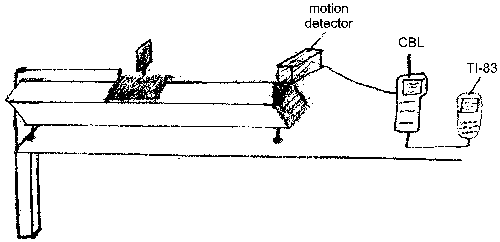
It all started with an experiment in my Physics class where we had to find the intensity of the acceleration of gravity. For this we used the airtrack with the "regular Vernier motion detector" attached to on end of it. The cart was connected via a string to a weight that pulled down the cart. We did this experiment several times with the following data:
The mass of the cart was 241.1g; the weight was 15.8g, 154.8N.
Since force = mass * acceleration; acceleration = Force / mass. The theoretical acceleration would be 154.8N / 241.1g = 0.64 m/s².
The first try was very good: 0.64m/s², but this must have been a mistake since then we got 0.56m/s² and 0.44m/s².
As you can see, this data is not very precise, so I asked myself what would be a precise way of measuring the acceleration of gravity. First, I analyzed the problems of the motion detector. One problem is the basic concept. The motion detector sends out an ultra-sonic wave and then measures the time it takes to travel to the object, be reflected and come back. Based on the speed of ultra-sonic waves, the detector calculates the distance. This process (I will call it the "reflection method") is very slow because the motion detector either has to wait for the wave to return or send the impulse at a certain rate and perhaps forget about not returning ones. This process is made worse by the fact that ultra-sonic waves "only" travel at a speed of 343 m/s (at standard pressure and room temperature) which slows it all down.
These considerations led to the assumption that the new measuring device should not use the "reflection method" and use faster waves. For not using the reflections, the "wave source" needs to be either stationary on the cart or at the end of the track. There are some waves that are faster than ultra-sonic waves. I first thought of radio waves. They are faster than ultra-sonic waves but have also one major disadvantage; their generation uses lots of energy.
While I was watching TV one day, an idea suddenly hit me: Why not use infrared light as remotes do? Infrared light is easy to generate with an infrared LED and also easy to measure with a photo diode. These considerations made infrared light "my waves".
This also shows that I use a completely different approach of measuring the distance. While the motion detector relies on the "distance = velocity * time"-formula, I calculate the distance with the "E=I/d²"-formula. This method is fairly simple. E is the symbol for illuminance or the rate at which light energy falls on a certain area. I is the luminous intensity, or the maximum energy a light source is able to produce. Unlike E, I is a constant.
At the beginning of each measuring process, the measuring unit needs to be calibrated. In order to this, the user puts the cart at a certain distance and a program reads E as an amount of voltage from the photo diode. Now, it calculates I (=d² * E). This can be repeated several times with different locations to get a more accurate calibration factor. After the measuring of the data, the voltage data gets converted to distance data with the formula distance = sqrt(luminous intensity / illuminance). I also decided to put the light source on the cart since it would be very impractical to put the photo diode with the "heavy" electronics on the cart.
My first "lab" was to check if the distance square formula works in "real life". For proofing that I took a regular light bulb, a photo diode, a digital multimeter and a meter stick. Then I moved the bulb back and forth, calculated the theoretical distance, compared to the measured one and came to the conclusion that the formula basically worked.
I also made an important observation: With the exact same distance, E would vary strongly. This had two causes. One was that the photo diode was not very accurate; buying a very precise one with a built-in amplifier solved this problem. The more important cause was that I was mainly measuring "normal" light (with a frequency of ca. 105 hertz); I had already solved this problem by deciding to use infrared light (very bright infrared LED). In order to further improve the reliability of the device, the photo diode was placed behind an infrared filter in a little box. These two steps led to a huge increase in reliability.
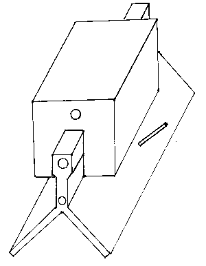
Now it was the time to think of constructing a box for putting the LED on the cart. The building of the box was a little bit tricky because it had to have a "U-shape" so that the additional weight of the batteries (2 AAs) does not let the cart wobble.

I improved the usability of the device I added an on/off-switch. For a better reliability the voltage of the two batteries is held constant by a voltage-stabilizer, so that the output of the LED is also constant.
The next step was to create the needed electronics. With the help of an assistant at the Applied Physics Lab of George Hopkins University, I planned the needed electronics.
The measuring electronics have two interfaces; one is very simple and the other one rather complicated. This is because of the two ways of analyzing the data I offer: either with a calculator (TI) or with a PC.
The method for the TIs is fairly simple. The commonly used CBL (Calculator Based Laboratory) is capable of measuring voltages; either with a range -10V to 10V or 0V to 5V. Since the CBL has a built-in 10bit A/D-converter, the resolution for the first case is 19.6mV and for the second one 5.6mV. Because of the better resolution, I chose the second one with the disadvantage that the photo diode's voltage output needs to be scaled to this range.
The method of processing the data for a PC is more complicated because the two ports a regular PC offers (serial and parallel interface) only accept digital data.

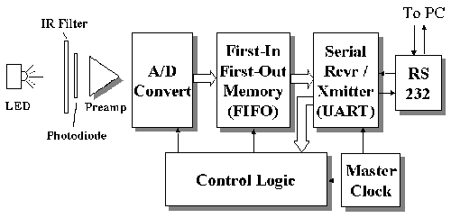
The data is scaled to the 0V to 5V range, too. Then it is being digitized with a 12bit A/D-converter and is afterwards cached in a FIFO memory. The measurement is controlled by simple logic circuitry that responds to serial commands sent from the PC. The commands allow the measurement to be started and stopped, and one of four sample rates may be selected. The logic also controls the readout of the FIFO following a measurement. Finally, the data is transmitted via the serial interface to the PC where a program that I wrote converts the voltages into distances. I intentionally kept the program simple because the analysis can be done much more easily and in a more sophisticated way with a spreadsheet.
Because of a lack of time, I could not finish my research and development so that it is unproven, if the newly developed device really works better than the motion detector.
My thanks go to Mr. Torsch, who explained a lot; to Mr. Fort, without whom the whole project would not exist; to the Science Department of Albert Einstein High School, which made this project financially possible; and to my host parents who provided me with tools, proofread this document and were helpful in many other ways.
d) Bibliography
Texas Instruments Incorporated. TI-83. 1996.
Texas Instruments Holland B.V.. CBL SYSTEM guidebook. Utrecht, 1996.